Introduction
A reliable and safe product is basic need of any investment. Product Certifications may demonstrate or depict quality, durability, safety and longer life of a product. A rigorous testing of a product affirms that products has achieved a specific benchmark of either performance or quality in accordance with the international standard(s).
Therefore, Solar photovoltaic (PV) Modules or commonly called, Solar Panels or Plates, must also confirm to a range of regulations and standards to Qualify before then can be considered for sale or installation at a specific location.
Once, PV Modules confirm to a design and qualification standard, installation practice must also adhere to the accepted practices or codes. Moreover, Solar photovoltaic panels and modern photovoltaic (PV) power plants and associated devices i.e. inverters need to support the electrical grid during electrical faults in the system and normal operation. Hence legislation, investors, operators and/or plant owners often require independent verification of solar plants and associated electrical equipment i.e. inverters, etc. before they are connected to the grid.
Though, every project or local regulatory authority i.e. local or state Government may have their own regulations or standards for any product which must be adhered to by installers or contractors, some generally required types of product certification are CE marking, FCC and CB Scheme.
CE: CE marking is a legal requirement allowing free trade of products within the EU/EEA. It represents a manufacturer’s declaration that a product complies with the minimum product safety, health, and environmental requirements of all relevant EU directives.
FCC: The FCC is a mandatory certification mark for electronic equipment and electronics that are manufactured or sold in the USA. This marking certifies that a specific product complies with standards of the Federal Communications Commission regarding electromagnetic interference.
CB: The CB Scheme is an international program established and operated by the International Electrotechnical Commission for Electrical Equipment (IECEE). The CB Scheme is a global system for mutual acceptance of product safety test reports and certificates. The IEC System for Conformity Assessment Schemes for Electrotechnical Equipment and Components (IECEE) Certification Body (CB) Scheme is the world’s first international system for the mutual acceptance of product safety test reports and certificates for electrical and electronic equipment, devices and components.
Field Failures in a Solar PV Module
A number of Solar PV module failures have been observed historically. Unfortunately, there is no such detailed data available currently. To evaluate long term performance outdoors and analyze failures, we really need outdoor performance data and failure data for at least 25 years. On the other hand we cannot wait 25 years to determine if a module is going to have a 25 year lifetime. Therefore, we have to utilize outdoor test data to develop Accelerated Stress Tests to determine which could be possible failures in a PV Module. When a PV Module is subjected to some rigorous testing then following failures are observed:
- Broken interconnects
- Broken cells
- Corrosion
- Delamination and/or loss of elastomeric properties of encapsulate
- Solder bond failures
- Broken glass
- Hot Spots
- Ground faults
- Junction box and module connection failures
- Structural failures
- Bypass Diode failures
- Open circuiting leading to arcing
In order to observe and analyze the failure modes, accelerated stress based tests are conducted to replicate the failures. Various tests are developed which primarily focus on increased thermal cycles, damp heating, freezing / cooling, UV exposure, mechanical loading, simulation of wind or snow, hot spot, hail test, bypass diode or salt spray. Historically, series of tests were developed to carry out failure mode analysis on PV Modules, and gradually industry came up with number of standards generally acceptable to the market. In this regard, IEC 61215 rapidly became the qualification test to pass in order to participate in the PV marketplace. Nevertheless, it can be stated that these tests may or may not be representative of standard real-world conditions. Moreover, most certification bodies may not regularly check up, or manufacturer may not get its product tested again after taking a particular Certificate once. Therefore, Certification may be prerequisite in a project, a further scrutiny of the manufacturer or seller is highly recommended before investment is made.
International Standards
Currently, manufacturer may certify its manufacturing process and Solar PV Module(s) to couple of standards depending upon its manufacturing location or to target the selling market. Solar Energy Industries Association (SEIA) USA published a reference list of the Standards in year 2016 for the PV Industry, and is nicely depicted here:
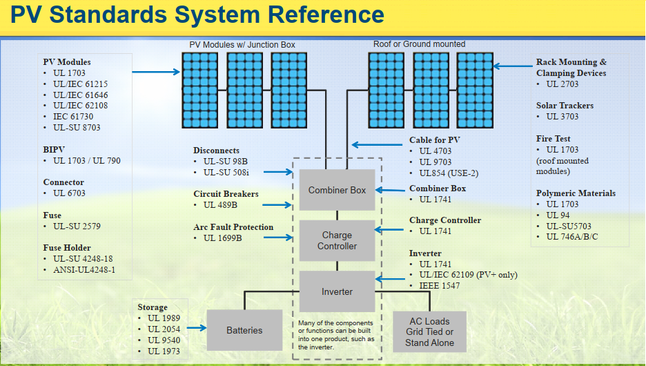
It can be seen that there is long reference of Standards applicable to the PV Modules and associated technologies. However, we shall discuss few of the Standards here as an introductory.
1) IEC 61215 Ed 2.0 – Crystalline Silicon PV Module Design Qualification and Type Approval
IEC 61215 lays down requirements for the design qualification and type approval of terrestrial photovoltaic modules suitable for long-term operation in general open air climates defined in IEC 60721-2-1. This standard is intended to apply to all crystalline silicon, mono and ploy both, terrestrial flat plate modules. The object of this test sequence is to determine the electrical and thermal characteristics of the module and to show, as far as possible within reasonable constraints of cost and time, that the module is capable of withstanding prolonged exposure in climates described in the scope. IEC 61215 tests do not address the particularities of PV modules with integrated electronics, it may however be used as a basis for testing such PV modules.
Part-1, IEC 61215-1, deals with the Test Requirements and Part-2, IEC 61215-2, focus on Testing Procedures. Various clauses/sub-clauses of part-1 of the Standard set requirements are Marking and Documentation, Visual Inspection, Maximum Power Determination, Insulation Test, Measurement of Temperature Coefficients, Measurement of Nominal Module Operating Temperature, Performance at STC and NMOT, Performance at Low Irradiance, Outdoor Exposure Test, Hot-Spot Endurance Test, UV Preconditioning, Thermal Cycling Test (requires Temperature Cycling between 85°C And -40°C, 50 or 200 times), Humidity-Freeze Test (requires Cycling between Hot/Humid 85°C/85%RH and Subfreezing -40°C Ten Times, with extended soaks at 85/85), Damp-Heat Test (requires a Long Term, 1,000 Hour, Test At 85°C/85%), Robustness of Termination Test, Wet Leakage Current Test, Static Mechanical Load Test, Hail Test, Bypass Diode Thermal Stabilization Test.
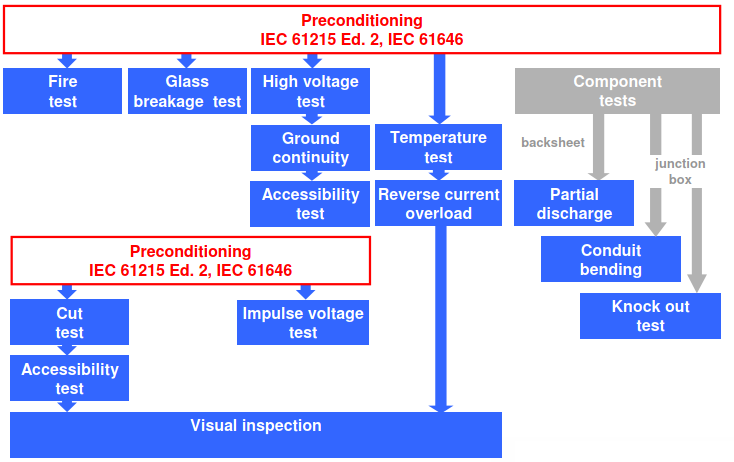
Test Sequence in IEC 61215

IEC 61215 tests also help determine a panel’s performance metrics at standard test conditions (STC), including temperature coefficient, open-circuit voltage, and maximum power output. For the standard IEC 61215 certification, 2400 Pa uniform load applies. However, if solar panels is to be installed in areas with heavy snow, an increased load capacity test of 5400Pa is advisable.
So what does it mean if a module type is qualified to IEC 61215 ? Passing the qualification test means the product has met a specific set of requirements. Those modules that have passed the qualification test are much more likely to survive in the field and not have design flaws that lead to infant mortality. Most of today’s commercial modules pass the qualification sequence with minimum change, meaning that they suffer almost no degradation in power output from the test sequence. In many markets today, conformance to IEC 61215 is a minimum requirement to participate in a project.
It is worth mentioning here that IEC 61215 does not address the reliability therein, thus the design qualification to such standards does not imply the PV module’s reliability. The lack of reliability standards is partially due to the fact that, to date, there are not enough statistical data collected from the PV fields. Moreover, such tests donot identify or quantify wear-out mechanisms, failure mechanisms for all climates and system configurations, differentiate between products that may have long and short lifetimes or quantify lifetime for the intended application/climate.
2) IEC61730 Ed. 2 – PV Module Safety Qualification
As with any electronic device, solar panels carry the risk of electrical shock if improperly built. That’s where IEC 61730 comes in. This standard address the safety aspects of a solar panel, encompassing both an assessment of the module’s construction and the testing requirements to evaluate electrical, mechanical, thermal, and fire safety and to show, as far as is possible within reasonable constraints of cost and time, that the module is capable of withstanding prolonged exposure in general open-air climates.
The object of this International Standard is to define the requirements for the construction of photovoltaic modules with respect to safe electrical and mechanical operation throughout their expected lifetime. These requirements are intended to minimize the misapplication and misuse of PV modules or the failure of their components which could result in fire, electric shock and personal injury.
At a commercial Solar PV Plant, DC voltage in a string of a PV Modules may go up to 1500 VDC in accordance with NEC. Therefore,
IEC 61730-1, Part 1: Specifies and describes the fundamental construction requirements for PV modules in order to provide safe electrical and mechanical operation. Specific topics assess the prevention of electrical shock, fire hazards, and personal injury due to mechanical and environmental stresses.
IEC 61730-2, Part 2: Outlines the testing sequence and procedues intended to verify the safety of PV modules whose construction has been assessed by IEC/UL 61730-1. The test sequence and pass criteria are designed to detect the potential breakdown of internal and external components of PV modules that would result in fire, electric shock, and/or personal injury.
have been developed and (recently) revised to include clear requirements developed for system voltages of up to 1500 VDC, including more stringent material and spacing requirements to reflect elevated operating voltages. The test sequences of the IEC 61730 are designed such that they can coordinate with those of the test procedures defined in IEC 61215. The revised edition of IEC 61730-1 brings additional clarity to the requirements for component level equipment used in the PV industry. Specifically, the changes means that components used in or on a PV module, for example, a junction box with cables and connectors, will also have to comply with the relevant component standards. In the case of this example, that would mean compliance with applicable standards for junction boxes (IEC 62790), cables (IEC 62930) and connectors (IEC 62852). By explicitly stating in the standard that such components must comply with applicable safety requirements, the revised IEC 61730-1 takes the necessary steps to promote safety of the entire PV module.
Test Sequence in IEC 61730
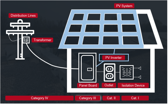
One of the key objectives in the revised version or 2nd edition of IEC 61730 was to align the concept of insulation coordination for PV modules with that presented in the IEC 60664 series of horizontal standards, “Insulation coordination for equipment within low-voltage systems.” Important factor focused in the revised version of the standard is to define the Overvoltage category for the PV Modules in line with the IEC 60664. PV installations must comply with these requirements, and PV modules are defined as Overvoltage Category III equipment, as per IEC 60664.
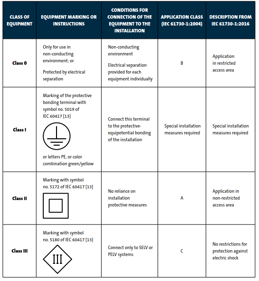
Another important consideration in the IEC 61730 2nd edition is to define equipment class. Four classes (Class 0, I, II and III) are defined in IEC 61140, “Protection against electric shock – Common aspects for installations and equipment.” The fundamental idea behind the classes is to categorize electronic equipment according to the respective methods used to protect against electric shock. The class definitions in the revised IEC 61730 Standards are now identical to those found in IEC 61140 i.e. Class 0, I, II & III.
The pollution degree (PD) is an important parameter that systematically evaluates the potential for pollution, such as dust and water, to collect on the surface of insulation, and to either compromise its effectiveness or make it conductive. Small clearances can be completely bridged by pollutants, such as solid particles, dust and water, which must be accounted for in meeting the minimum clearance requirements. To design a product that meets the required clearance and creepage distances, the micro-climate must be assessed first. IEC 60664-1 identifies four degrees of pollution, ranging from pollution degree 1 (PD=1) to 4 i.e. 1 having the least protection. Now, PV modules may be exposed to a variety of climates with very different temperatures and various levels of humidity, rain, dust, contaminants and irradiance. Based on the definition of pollution degree from IEC 60664-1 and knowledge of the intended installation location, PV modules should generally be designed to withstand at a minimum conditions of a PD=3 microenvironment. However, the challenge, remains to design a PV module that allows for a reduction in the applicable PD. In cases where the enclosure provides component protection equal to or greater than an ingress protection IP55 rating, the applicable PD may be reduced to PD=2. For components and parts within an enclosure satisfying the relevant requirements specified in Annex C of IEC 61730-1, the applicable PD may be reduced to PD=2 or even PD=1.
Breakdowns on the surface of insulating materials between conductive parts can compromise the insulation. To address this potential concern, insulating materials are characterized with respect to their surface tracking behavior. The comparative tracking index (CTI) is a material specification, originally developed by UL, with variations of the index also used in several IEC standards. Insulating materials are categorized into one of four groups, from Group lllb to l, with Group I materials demonstrating the greatest resistance to track formation. Hence, material selection of insulation in PV module is important consideration during design and manufacturing, and is well addressed in the revised IEC 61730.
Note: As of December 4, 2019, all new or modified PV modules to be installed in the United States must transition from UL 61730 and UL 1703 or should comply to harmonized IEC/UL 61730 standard. As of January 1, 2020, the California Energy Commission (CEC) will only accept listing requests that include module certification to IEC/UL 61730. The harmonized IEC/UL 61730 photovoltaic safety standard for international and North American markets now allows manufacturers to avoid the costly and time-consuming process of having products evaluated to multiple safety standards and can utilize compliance to IEC/UL 61730 for a streamlined approach for greater access to a more global marketplace.
3) UL1703 – PV Module Safety Qualification
UL 1703, “The Standard for Flat-Plate Photovoltaic Modules and Panels,” was largely based on the California Institute of Technology’s Jet Propulsion Laboratory (JPL) block-buy module development and test experience. Underwriters Laboratories (UL) has been the mostly used US-body to certify solar panels for the US market and issues the prominent UL 1703 certification in recent years. Later on, UL 1703 led to the development of the first edition of the IEC 61730 to supplement the type approval standards IEC 61215.
Standard requirements cover flat-plate photovoltaic modules and panels intended for installation on or integral with buildings, or to be freestanding (that is, not attached to buildings), in accordance with the National Electrical Code, NFPA 70, and Model Building Codes. Important part of the Standard includes Fire Test Section or Type tests for fire performance characterization of modules and panels independent of roof coverings and System Fire Class Rating of module or panel with mounting systems in combination with roof coverings.
It is worth mentioning here that after the 2013 changes to ANSI/UL 1703, the fire classification rating approach takes into account the module or panel in combination with the mounting system and the roof covering products over which it is installed.
One section of the standard requires Fire Testing of the PV modules to be conducted once with both the Spread of Flame and Burning Brand on Top of Surface tests. Both of the tests are based on the ignition flame being directed on the top surface of the module or panel with no roof covering below. The Burning Brand on Top Surface test uses a specific type of brand (A, B, or C) as specified by the “Type” of module or panel being tested.
Another Section deal with Fire Testing to conclude the System Fire Class Rating of a module or panel with mounting systems in combination with roof coverings. The two types of roof slopes are Steep-Sloped (> 2in/ft slope) and Low-Sloped (< 2in/ft slope) and can be configured in a Symmetrical or Asymmetrical configuration of the roof slope. Both of the Spread of Flame and Burning Brand Tests are required for the Steep-Slope. From a safety perspective, the goal is that the installation of a stand-off mounted PV module and its mounting system does not degrade the fire class rating of the roof assembly.
These requirements do not cover:
- Equipment intended to accept the electrical output from the array, such as power conditioning units (inverters) and batteries;
- Any tracking mechanism;
- Cell assemblies intended to operate under concentrated sunlight;
- Optical concentrators; or
- Combination photovoltaic-thermal modules or panels.
KEY DIFFERENCES BETWEEN UL 1703 AND UL 61730-1 AND UL 61730-2
| STANDARD REQUIREMENTS | UL 1703 | UL 61730-1 & UL 61730-2 |
| Construction and Testing | One document, UL 1703, refers to construction evaluation of the product and its testing | Two documents -UL 61730-1 refers to construction evaluation of the product and UL 61730-2 refers to its testing |
| Number of Test Sequences | 4 | 8 |
| Design Load | 30 psf or 1436 Pa | 50.12 psf or 2400 Pa |
| Fire Type | Up to Type 15 | Up to Type 33 |
| California Energy Commission | Will not accept UL 1703 certification for new products starting January 1, 2020 | Accepted starting January 1, 2020 |
| NEC 2020 | Referenced | Referenced |
4) IEC 61646 – Thin Film PV Modules Design Qualification and Type Approval
This International Standard lays down requirements for the design qualification and type approval of terrestrial, thin-film photovoltaic modules suitable for long-term operation in general open-air climates as defined in IEC 60721-2-1. This standard is intended to apply to all terrestrial flat plate module materials not covered by IEC 61215. The test sequence is derived from IEC 61215 for the design qualification and type approval of terrestrial crystalline silicon PV modules. Similar to IEC 61215, IEC 61646 includes rigorous testing of Thermal cycling, humidity-freeze and Damp Heating.
5) IEC 61701 – Salt Mist Corrosion Type Test Approval
Highly corrosive wet atmospheres, such as marine environments or locations near the ocean or other large bodies of salt water, could eventually degrade some of the PV module components (corrosion of metallic parts, deterioration of the properties of some non-metallic materials – such as protective coatings and plastics – by assimilation of salts, etc.) causing permanent degradation that could impair their functioning.
This standard describes test sequences useful to determine the resistance of different PV modules to corrosion from salt mist containing Cl (NaCl, MgCl2, etc.). All tests included in the sequences are fully described in IEC 61215-2, IEC 62108, IEC 61730-2 and IEC 60068-2-52.
The salt spray test is a standardized test method used to check corrosion resistance of coated samples. Salt spray test is an accelerated corrosion test that produces a corrosive attack to the coated samples in order to predict its suitability in use as a protective finish. IEC 61701 for photovoltaic modules specify the duration and ambient temperature of the test with a module of specific inclination. Acceptance criteria are the same as those of IEC 61215 and no corrosion of modules parts that may influence module safety and functionality. Normally the time required for the test depends on the level of severity. Severities are 1 (marine environments) and 2-3-4-5-6 (environment with changes between salt and dry atmosphere).
The bypass diode functionality test is also included in this type test. This evaluates possible faults caused in PV modules when operating under wet atmospheres having high concentration of dissolved salt (NaCl). Depending on the specific nature of the surrounding atmosphere to which the module is exposed in real operation several testing methods can be applied, as defined in IEC 60068-2-52.
6) IEC 62716 – Ammonia Corrosion Type Test Approval
The ammonia corrosion test has been developed for modules that are installed on livestock farms and greenhouses are subjected to particular environmental conditions that may be very harsh, in particular fertilizing, ammonia and where dust particles can develop in the environment. The concentration of ammonia, which is a harmful substance released into the air in large amounts on farms, may be very high and these emissions can additionally increase aging (degradation) of the photovoltaic modules.
This standard describes test sequences useful to determine the resistance of PV modules to ammonia (NH3). All tests included in the sequences, except the bypass diode functionality test, are fully described in IEC 61215, IEC 61646 and IEC 61730-2. They are combined in this standard to provide means to evaluate possible faults caused in PV modules when operating under wet atmospheres having high concentration of dissolved ammonia (NH3).
7) IEC 62804 –Type Test Approval to detect Potential induced degradation (PID)
Potential-induced degradation (PID) refers to any PV module degradation that is caused by the stress of an electric potential between the active cell circuit and the external surfaces or parts of the PV module. This part of IEC 62804 is for testing and evaluating the durability of crystalline silicon PV modules for PID in the mode of delamination (PID-d), as may be induced by the stress factors of moisture and system voltage. Delamination of PV modules is a failure mode that can lead to electrical shocks, ground faults, rapid moisture ingress or collection of condensed moisture and can be associated with corrosion, some loss in photocurrent and hotspots due to degraded transmission of light to the solar cells, and visual undesirability. Various delamination modes are seen occurring in fielded modules for which standardized methods for accelerated testing do not exist to predict these vulnerabilities.
8) IEC 60904-1 – Measurement of PV Current-Voltage Characteristics
This part of IEC 60904 describes procedures for the measurement of current-voltage characteristics (I-V curves) of photovoltaic (PV) devices in natural or simulated sunlight. These procedures are applicable to a single PV solar cell, a sub-assembly of PV solar cells, or a PV module. They are applicable to single-junction mono-facial PV devices. For other device types, reference is made to the respective documents, in particular for multi-junction devices to IEC 60904-1-1 and for bifacial devices to IEC TS 60904-1-2.
This standard is applicable to non-concentrating PV devices for use in terrestrial environments, with reference to (usually but not exclusively) the global reference spectral irradiance AM1.5 defined in IEC 60904-3. It may also be applicable to PV devices for use under concentrated irradiation if the application uses direct sunlight and reference is instead made to the direct reference spectral irradiance AM1.5d in IEC 60904-3.
The purposes of this document are to lay down basic requirements for the measurement of I-V curves of PV devices, to define procedures for different measuring techniques in use and to show practices for minimizing measurement uncertainty. It is applicable to the measurement of I-V curves in general. I-V measurements can have various purposes, such as calibration (i.e. traceable measurement with stated uncertainty, usually performed at standard test conditions) of a PV device under test against a reference device, performance measurement under various conditions (e.g. for device temperature and irradiance). I-V measurements are also important in industrial environments such as PV module production facilities, and for testing in the field.
9) NFPA-70 – National Electric Code – 2020
National Electric Code article 690 applies to solar PV systems including the array circuit(s), inverter(s), and controller(s) for such systems which may be interactive with other electrical power sources (electric utility) or stand-alone with or without energy storage (batteries). Article 690 focuses on reducing the electrical hazards that may arise from installing and operating a solar photovoltaic system, to the point where it can be considered safe for property and people.
NEC sets the safe practices of design, installation and working in regard to Solar PV Modules in association with other system components such as PV cables, supporting structure, disconnects, over-current devices, raceways, outlet, junction boxes, inverter or similar fittings as part of the System.
This article, NEC 690, consists of eight parts, but the general requirements of Chapters 1 through 4 of NEC also apply to these installations, except as specifically modified by Article 690.
NEC 690 sets requirements of voltage limitations for dwellings, buildings or non-building installations, other than article 691 (dealing with 5000 KW or bigger installation). Beside that it specifies the circuit sizing i.e. cable, disconnect, over-current protection, etc. In addition to that, Photovoltaic systems operating at 80 volts dc or greater between any two conductors shall be protected by a listed PV arc-fault circuit interrupter or other system components listed to provide equivalent protection. One of important aspect of NEC 690 is to have Rapid Shutdown System with an initiation device at a readily accessible location in building installations to help fire fighters quickly isolate/disconnect the system. Moreover, Grounding and Bonding, Wiring methods with associated materials and Labelling / Marking of system components are also addressed to have safe practices.
Beside article 690, other pertinent articles of NEC applicable to Solar PV systems include 240: “Over Current Protection”, 250: “Grounding and Bonding”, and 705: “Interconnected Electric Power Production Sources”.
Currently, most of the States or Authorities Having Jurisdiction (AHJ) in United States require compulsory compliance to NEC code either 2017 or 2020, as advised locally.
REFERENCES:
- “Solar Standards Development: An Overview of Product Standards” by SEIA; July 2016
- “Fire Classification Rating Testing of Stand-Off Mounted Photovoltaic Modules and Systems” by Solar ABC; August 2013
- “The Dawn of New PV Safety Requirements: IEC 61730 2ND EDITION” by Underwriter Laboratories
- “Design Qualification and Test Approvals of Solar PV Modules” by TUV
- “PV Panels & Modules : IEC/UL 61730 Compliance” by Intertek
- “Transitioning to UL 61730-1 and UL 61730-2 from UL-1703” by Q-Cells
- NFPA 70 – National Electric Code – 2020
AUTHOR:
Asif Khokher is seasoned professional having 24 years of international and diversified experience in the field of Control Systems, SCADA and Solar PV for Power, Oil & Gas, utility and other industries serving with International Consultants, Contractors and Sub-contractors/Suppliers/System Integrator. He is currently based in Pakistan, and works as Consultant/Auditor/Inspector and Owner’s Engineer and can be reached at asif.khokher@innovasyses.com
His educational background is B.Sc. Engineering (Electrical), MBA and North American Board Certified Energy Practitioner (NABCEP – PV Installation Professional) beside Project Management Professional (PMP) and Certified Automation Professional (ISA-CAP).