As #Grounding and #Bonding is a subject that blurs many to a large extent so it would be good to have a summary of key points according to #NEC. NEC is the primary guiding document for the safe designing and installation practices of #Solar #PV systems in the residential and commercial markets of USA. Summary or guideline outlined below can be used by a Solar PV practitioner, however, it is highly recommended that section 690.41, 690.42, 690.43, 690.45 and 690.47 be always read in conjunction with section 240 of NEC. Major points to remember are:
1) Ground Fault current always needs an effective return path back to the source. Equipment Grounding Conductor (EGC) provides such path in most of the cases. In this regard, Main Bonding Jumper (MBJ) should be installed to connect the EGC to the neutral of the supply at one point only. See Figure below. This is true for a solidly grounded system.
2) Connection of grounding and bonding of Equipment Grounding Conductor (EGC), Grounding Electrode Conductor (GEC), Bonding Jumpers at any point or mounting PV modules should be carried out through listed devices, systems i.e. connectors, terminal bars, etc.
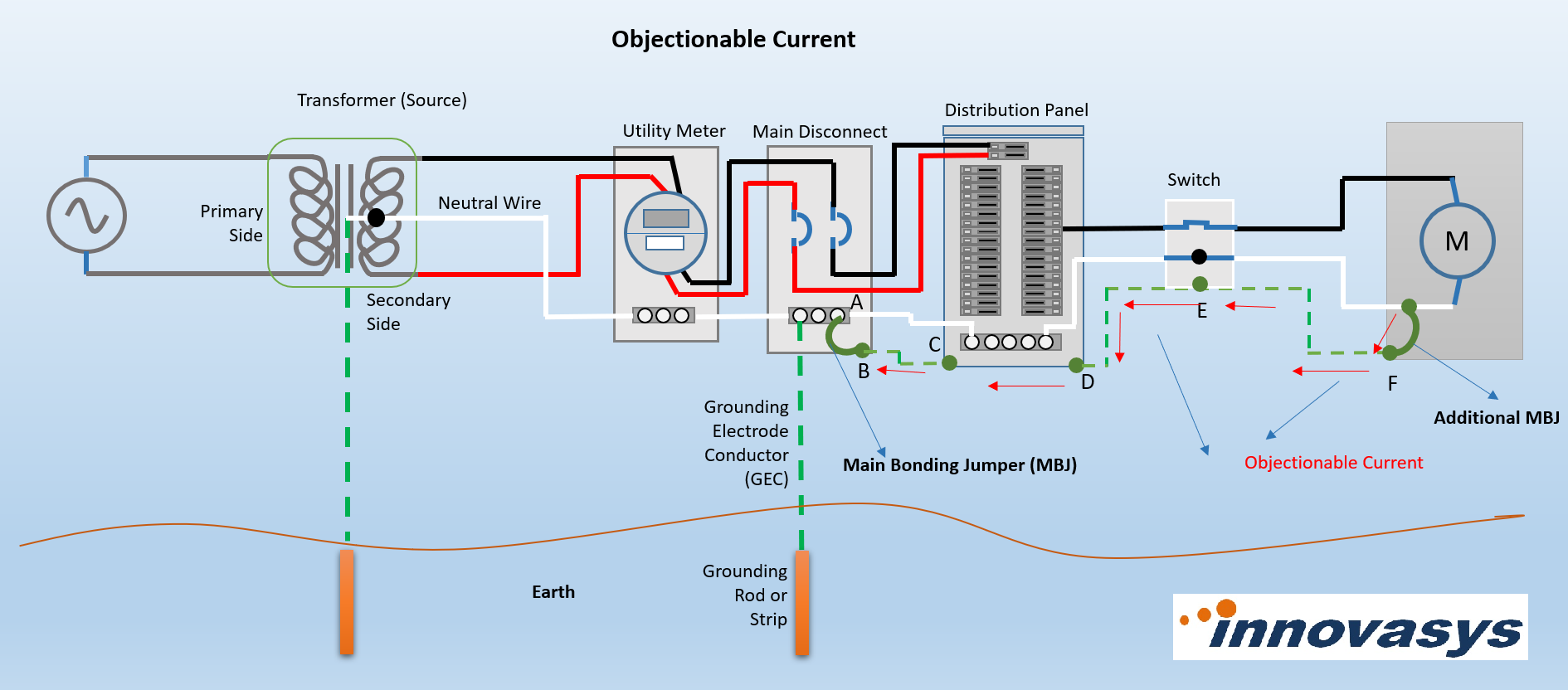
3) It is recommended that Main Bonding Jumper (MBJ) and Grounding Electrode Conductor (GEC) are connected together at the same point i.e. grounding bus-bar inside Main Disconnect or Distribution Panel of a residential or building facility. Connecting neutral to the EGC at multiple points will lead to objectionable current. See Figure below. Objectionable current occurs when there are multiple paths for the return current and current start flowing back to the source though the grounding conductor (EGC) or body of an equipment under the normal circumstances (no fault-current existing) as shown in the Figure below. This happens due to the having more than one Main Bonding Jumpers.
4) Description and Types of Grounding Electrode systems are provided in Section 250.50 and 250.52 of NEC. Effort should be made that Grounding Electrodes are buried below the permanent moisture level in the earth. Major types are:
i) Metal underground water pipe: Underground metal water pipe in direct contact with the earth for 10 ft or more
ii) Metal in-ground support structure: Metal in-ground support structure(s) in direct contact with the earth vertically for 10 ft or more
iii )Concrete-encased electrode (ufer): One or more electrically conductive steel reinforcing bars of not less than ½ in of diameter and 20ft in length, or Bare copper conductor not smaller than 4AWG of 20 ft or greater length (any of these should be encased at least 2 in)
iv) Ground Ring: A ground ring consisting of at least 20 ft of bare copper conductor not smaller than 2 AWG buried in earth
v) Grounding Rod: This is the most commonly used type of grounding or earthing electrode. It must have at least 3/8 in of diameter and 8 ft in length buried in the earth
vi) Plate Electrode: Bare or electrically conductive coated iron or steel plate with not less than ¼ in of thickness, or solid uncoated copper metal plate not less than 0.06 in of thickness, with an exposed surface area of 2 sq. ft.
5) If a supplemental grounding electrode or rod is used then it should be separated at least by 6 ft from the main grounding electrode.
6) Aluminium conductors are not allowed as GEC.
7) Size of the GEC is found out using the section 250.66 and Table 250.66 of NEC. This essentially means that size of the GEC is dependent upon the size of the largest ungrounded current-carrying conductor in the system.
8) If size of the GEC is smaller than 6 AWG then it must be protected in a metal, intermediate metal or PVC conduit. If size of the GEC is 6 AWG or greater and is exposed to physical damage then again should be protected in conduits. Moreover, splicing in GEC are not allowed except the permitted methods.
9) If there are multiple buildings or structures having their own grounding system or GEC then all should be combined or connected at one common place i.e. bus bar and eventually connected to a common Grounding Electrode.
10) Exposed Metal parts of fixed equipment likely to become energized must be connected to the circuit Equipment Grounding Conductor.
11) Types of EGC can be wire type, rigid metal conduit, intermediate metal conduit, electrical metal tubing or part of metal-clad cable as discussed in the section of 250.118 of NEC.
12) Size of the EGC is determined through the section 25.122 and Table 250.122 of NEC. This essentially means that that size of the EGC is dependent upon the size of the Over-Current Protection Device (OCPD) in the PV circuit(s). However, it is not required to be larger than the size of the current carrying circuit conductor(s). If size of the current conductors is increased to cater the voltage drop then size of the EGC is not required to be increased except as sized according to OCPD and Table 250.122.
13) EGC smaller than 6 AWG should be protected from physical damage by installing these in a raceway or cable armor. It should run with the circuit or current carrying conductor in the same raceway or cable when it leaves the vicinity of the PV array.
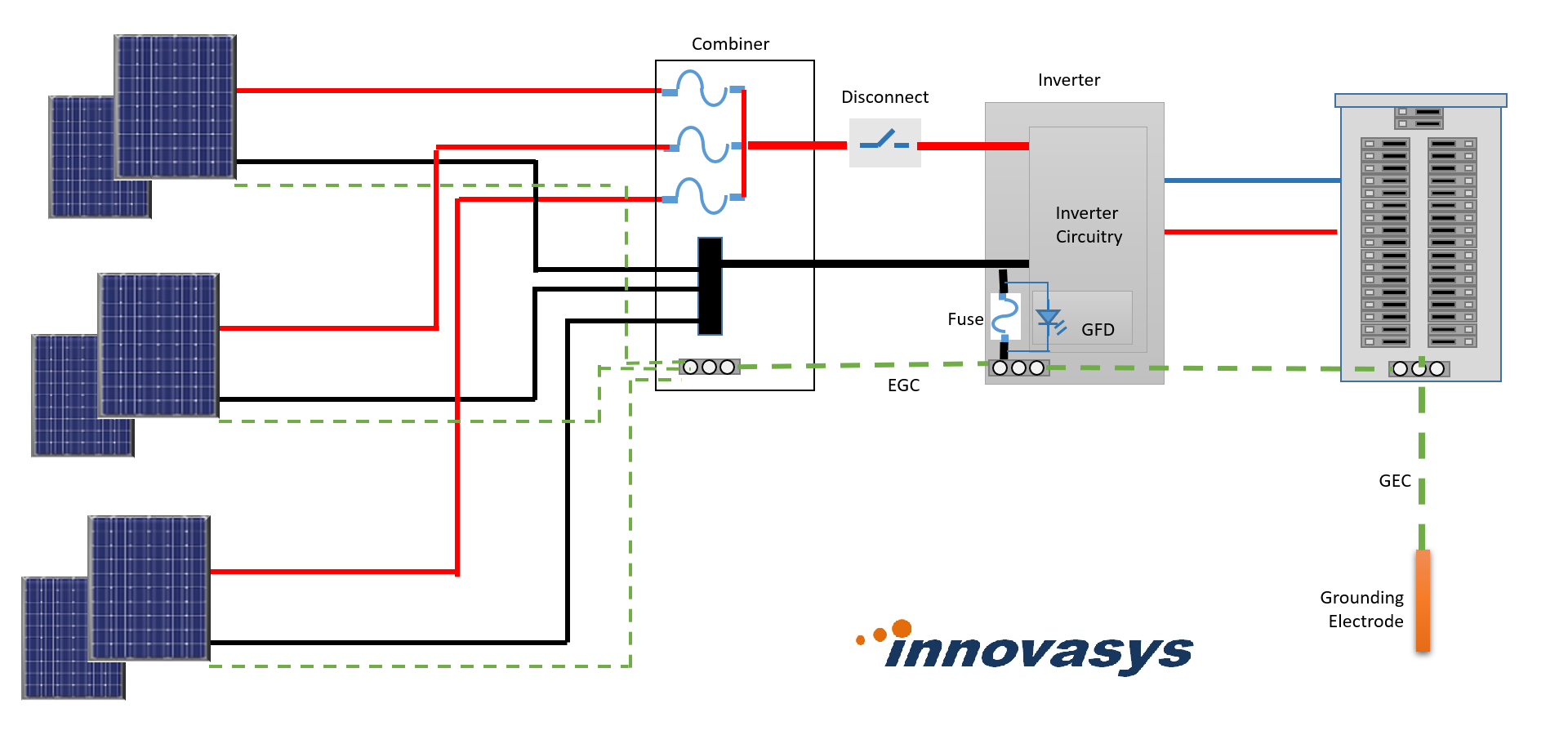
14) Now a days, a functionally grounded Inverters or PV arrays not isolated from the grounded output circuit of inverter are used. This allows that the EGC of the PV circuit is connected to the grounding point provided by the inverter, eliminating the need of separate DC grounding system. Grounding point of Inverter is connected onwards to the grounding system or grounding electrode of the residential facility or building. See Figure below.
15) PV circuits having 30V or 8A more shall be provided with Ground-Fault Protection Device (GFPD). Now a days, in general, this is an in-built function of the inverters. GFD should be listed for the purpose. GFD shall disconnect the faulted circuit from rest of the circuit and stop inverter supplying output power. In this regard, Inverter should be listed to UL1741.
16) GFD is not required for the PV circuit which is not installed on a building, is solidly grounded and there are not more than two PV circuits connected in parallel.
17) Exposed metal parts, equipment or supporting structure in the PV circuit likely to become energized should be connected to grounding system or EGC in accordance with the NEC article 250.104, 250.134 and 250.136. Devices and equipment which are used to support or mount the PV modules or equipment, and which eventually are required to be connected to the EGC shall be listed, labeled and identified for the purpose of bonding to the grounding system in accordance with UL2703. UL2703 listed bonding components helps reduce installation time and ensure required bonding strength.
Note: Lightening Protection System and associated grounding system should be designed in accordance with the NFPA 780 as stated in the 250.106 of NEC.
Author:
Asif Khokher is seasoned professional having 24 years of international and diversified experience in the field of Control Systems, SCADA and Solar PV for Power, Oil & Gas, utility and other industries serving with International Consultants, Contractors and Sub-contractors/Suppliers/System Integrator. He is currently based in Pakistan, and works as Consultant/Auditor/Inspector and Owner’s Engineer and can be reached at asif.khokher@innovasyses.com
His educational background is B.Sc. Engineering (Electrical), MBA and North American Board Certified Energy Practitioner (NABCEP – PV Installation Professional) beside Project Management Professional (PMP) and Certified Automation Professional (ISA-CAP).